Table of Contents
Aircraft Controller
Setup Guide
Step-by-step Setup
This tutorial will describe setting up Cirrus SR22 in an empty Unity scene. The end result scene of the guide is included in the project and is named TutorialScene.
Cirrus SR22 model can be found under NWH ⇒ Aerodynamics ⇒ Models directory.
Reading the Airfoil documentation before starting the aircraft setup is highly recommended
Scene Setup
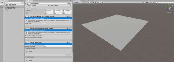
- Create a new empty
Scene.
- Create a new empty
GameObjectand name it SceneManager.
- Attach
InputSystemAircraftInputProviderandInputSystemSceneInputProvider- these will handle the user input.
- Attach
ShiftingOriginto SceneManager - more about shifting origin here.
- Add a
Terrainto the scene and position it at [-500, 0, -500] to center it.
Aircraft Controller
- Drag NWH ⇒ Aerodynamics ⇒ Models ⇒ Cirrus SR22.fbx into the middle of the newly created scene.
- Select all the colliders in the hierarchy (Cirrus SR22 ⇒ Colliders) and disable/untick
MeshRendereron them. AddMeshColliderto all four. It is important that a Rigidbody has at least one collider.
- Add
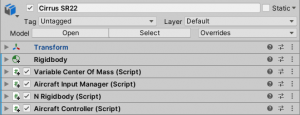
AircraftControllerto the parent object (Cirrus SR22 in this case). This will add other required components automatically.
- In the
Variable Center Of Massinspector adjust theBase Massto 1000 and set theCenter Of Mass Offsetto [0, -0.18, 0.9].
- Untick
Use Default Inertiaand adjust theDimensionsfield if required. Dimensions are displayed as gizmo lines. Red for width, green for height and blue for length. After adjusting the dimensions clickUpdate Inertia Tensor.
That is it for the core aircraft setup. The next step is making the aircraft fly.
Cameras
- Create an empty GameObject that is a child of Cirrus SR22 and call it Cameras.
- Attach
CameraChangercomponent to the newly created object.
- Create a new
Cameraand parent it to the Cameras object and addCameraMouseDragcomponent to it.
- Adjust the
Distancefield ofCameraMouseDragto 10.
- Press play and check if the camera works properly. LMB to rotate, RMB to drag.
Airfoils
- Follow the setup guide on Airfoil page to set up Cirrus SR22 ⇒ FlightSurfaces.
- Follow the setup guide on ControlSurfaces page to set up Cirrus SR22 ⇒ FlightControlSurfaces.
- Press play. Try pressing W and S to test out the elevators, A and D to test the ailerons and Q and E to test the rudder.
- Place the aircraft at the height of 1000 meters above terrain and press play. Let the aircraft gain some speed and try controlling it using WASD.
Tips:
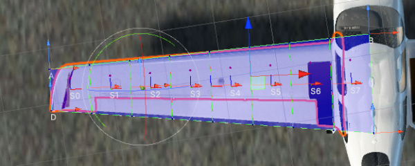
- When setting up an aircraft the wing
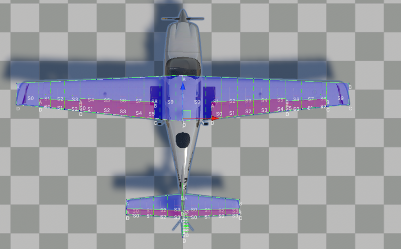
Airfoils should extend up to roughly the centerline of the aircraft as in the image above. - Airfoils should cover the control surfaces belonging to them.
To test out the setup place the aircraft 500m above the ground and press play. It should slowly tip forward and gain speed.
Once the Airfoils are set up as per the instructions above the aircraft should look like this:
Aerodynamic Drag Objects
Besides airfoils aircraft also have objects that contribute little or nothing to lift, but do cause drag. In NWH Aerodynamics these can be set up using AerodynamicDragObject.
- Attach
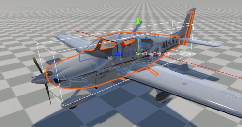
AerodynamicDragObjectcomponent to the Fuselage object.
- Adjust the
CenterandDimensionsso that the box gizmo roughly matches the shape of the fuselage.
Landing Gear
After pressing play, currently the aircraft drops to the ground. To prevent this we need to add the landing gear.
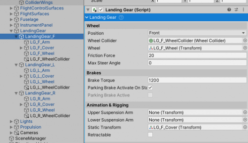
- Add
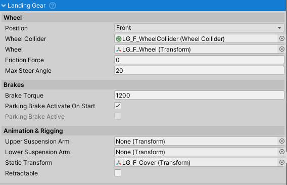
LandingGearcomponent to LandingGear_F, LandingGear_L and LandingGear_R.
- Adjust the
Positionfield to match the position of the landing gear.
- Duplicate LG_F_Wheel, LG_L_Wheel and LG_R_Wheel and rename them to LG_F_WheelCollider, LG_L_WheelCollider and LG_R_WheelCollider. Remove
MeshFilterandMeshRendererfrom the duplicated objects. These will act as holders forWheelCollider.
- Drag the duplicated objects so they are slightly above the wheels.
- Attach
WheelColliderto all three duplicated objects and adjust theRadiusfield until the gizmo matches the wheel size.
- Press play. The aircraft should not stand on the landing gear.
- Assign the created
WheelCollidertoWheel Colliderfield ofLandingGearcomponent added in first step. Also assign the corresponding wheel meshes to theWheelfield (LG_F_Wheel to LandingGear_F, etc.).
- Set the
Max Steer Angleto 10 for the LandingGear_F. This value can be set to 0 for wheels that do not steer, a positive value for normal steering, or a negative value for inverse steering (e.g. rear wheel).
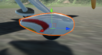
- Assign the LG_F_Cover to the
Static Transformfield.
The landing gear for Cirrus SR22 is now set up. For more details on LandingGear check out this page.
Propulsion
The final step to setting up a functional aircraft is adding propulsion.
Cirrus SR22 is propelled by a piston engine connected to a variable-pitch propeller so PistonEngine and PropellerPropulsor will be used.
- Under Propulsion create a new empty GameObject called Engine. This object will contain all the engine-related components.
- Add
PistonEngineto the Engine object and set theMax Powerto 400 andStarter Torqueto 150.
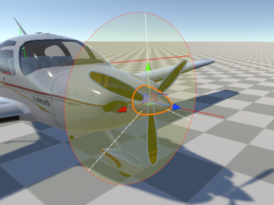
- Add
PropellerPropulsorthe the Propeller object and assign it to thePropulsorsfield ofPistonEngine.
- If needed adjust the
Thrust PointandThrust Directionof thePropellerPropulsor.
- Since Cirrus SR22 has a variable pitch propeller tick
Variable Prop Pitch. Also tickAuto Prop Pitch.
To test the propulsion enter play mode and hold the T key for 2 to 3 seconds to start the engine. Afterwards, press F4 to increase the throttle to 100%. After gaining some speed the aircraft will be able to take off.
Sound
The aircraft is now fully functional but is lacking sound.
- Add
AircraftSoundManagerto the aircraft.
- Attach
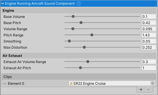
EngineStartingAircraftSoundComponentandEngineRunningAircraftSoundComponentto the Engine object.
- Attach
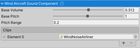
WindAircraftSoundComponentandCrashAircraftSoundComponentto the Cirrus SR22 object. These can be placed anywhere on the aircraft.
Press play to test out the sounds.
Readouts
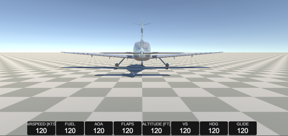
For testing purposes a DemoReadouts component can be helpful as it shows the basic flight data. This step is optional but recommended.
- Create a new UI
Canvasand create a childPanel.
- Adjust the panel so that it covers the whole canvas and remove the background
Image.
- Attach
DemoRedoutsto the panel and set theReadout Prefabfield to NWH/Aerodynamics/Scripts/AircraftController/Demo/Readout.prefab.
- Add
Grid Layout GroupwithCell Sizeof [100, 50] to the panel.
- Add Cirrus SR22 to the
Target AC.
Pressing play will now produce a row of basic flight data readouts.
Wrapping Up
The basic aircraft setup is now finished. For steps on setting up other optional aspects of the aircraft such as lights, instruments and fuel check out their respective pages:
Input
AircraftInputManagerretrieves input from activeInputProviderand fills theInputStatesstruct with the retrieved data.InputProviders are split into AircraftInputProviders and SceneInputProviders. AircraftInputProviders relay vehicle input (throttle, yoke, etc.) while SceneInputProviders take care of scene input (vehicle changing, camera changing, camera movement and the rest of the inputs not directly related to vehicle. One of each needs to be present (e.g.InputSystemVehicleProviderandInputSystemSceneInputProvider).- Multiple different
InputProviders can be present in the scene. E.g. InputSystemProviders and MobileInputProviders can be used in the same scene. The resulting input will be a sum of inputs from allInputProviders in case of numeric inputs and logical OR operation of all inputs in case of boolean inputs. - Input is stored inside the
InputStatesobject and can be copied over from one vehicle to another. E.g. this is what is done when a trailer is connected to a towing vehicle. - To manually set the
InputStatesmake sureAuto Settableis set to false.
All input providers inherit from either AircraftInputProviderBase or SceneInputProviderBase, but differ in their implementation.
Input System Warning
When importing the asset for the first time this message will pop up:
Both Yes or No can be selected but it is important to set the Project Settings ⇒ Player ⇒ Input Handling to Both afterwards. This way both new InputSystem and the old InputManager will work. If this setting is set to InputManager only errors might appear as the demo scenes of the asset rely on InputSystem.
If a message This Unity Package has Package Manager dependencies. appears, click Install/Upgrade.
Available Bindings
AircraftInput Provider Bindings
Out of the box gamepad bindings are only available for InputSystem.
| Name | Type | Keyboard Defaults | Gamepad Defaults |
|---|---|---|---|
Ailerons | axis | A/D | LS - Horizontal |
AileronsTrimLeft | button | H | Button North + Right |
AileronsTrimRight | button | K | Button North + Left |
Rudder | axis | Q/E | L/R Trigger |
RudderTrimLeft | button | Y | |
RudderTrimRight | button | I | |
Elevator | axis | W/S | LS - Vertical |
ElevatorTrimUp | button | U | Button North + Up |
ElevatorTrimDown | button | J | Button North + Down |
FlapsExtend | button | F7 | Right Shoulder |
FlapsExtendFully | button | F8 | |
FlapsRetract | button | F6 | Left Shoulder |
FlapsRetractFully | button | F5 | |
Spoilers | button | / | |
LandingLights | button | L | |
NavigationLights | button | K | |
LandingGear | button | G | |
EngineStartCommon | button | T | Button West |
EngineStopCommon | button | F | Button North + West |
ThrottleCommon | axis | F12 | |
ThrottleIdle | button | F1 | |
ThrottleIncrease | button | F3 | Button South |
ThrottleDecrease | button | F2 | Button North |
ThrottleFull | button | F4 | |
ParkingBrake | button | , | Button North + East |
Brakes | button | . | Button North |
BrakesLeft | button | - | |
BrakesRight | button | = | |
SmokeSystem | button | I | |
PropPitch | axis | F9/F10 | |
PropPitchIncrease | button | F12 | |
PropPitchDecrease | button | F11 |
Scene Input Provider Bindings
| Name | Type | Keyboard Defaults | Gamepad Defaults | Description |
|---|---|---|---|---|
ChangeCamera | button | C | Start | Changes camera. |
CameraRotation | 2D axis | Mouse Delta | Right Stick | Controls camera rotation. |
CameraPanning | 2D axis | Mouse Delta | Right Stick | Controls camera panning. |
CameraRotationModifier | button | Mouse - LMB | Right Stick Press | Enables camera rotation. |
CameraPanningModifier | button | Mouse - RMB | Left Stick Press | Enables camera panning. |
CameraZoom | axis | Mouse - Scroll | D-Pad Up/Down | Camera zoom in/out. |
ChangeVehicle | button | V | Select | Change vehicle or enter/exit vehicle. |
FPSMovement | 2D axis | WASD | Left Stick | Demo FPS controller movement. |
ToggleGUI | button | Tab | Toggles demo scene GUI. |
Input Manager (old/classic)
- Type of
InputProviderfor handling user input on desktop devices through keyboard and mouse or gamepad. - Uses classic/old Unity Input Manager. It is recommended to use the Unity's new Input System instead for new projects.
InputSystem package is required even if not used. If using the old/classic Unity input set Project Settings ⇒ Player ⇒ Input Handling to Both and proceed as normal. InputSystem package being present installed will not interfere with old/classic Unity input / InputManager.
Installation
When first importing NWH Aerodynamics the project will be missing the required bindings in Unity Input Manager. There are two ways to add those:
- Manually adding each entry to the Project Settings ⇒ Input following the input bindings table.
- Copying the contents of InputBindings.txt and appending them to the contents of the
[UnityProjectPath]/ProjectSettings/InputManager.assetfile. To do so:- Close Unity.
- Open InputManager.asset in a text editor of your choice.
- Copy the contents of the provided InputBindings.txt file (NWH ⇒ Aerodynamics ⇒ Scripts ⇒ Input ⇒ InputProviders ⇒ InputManagerProvider ⇒ InputBindings.txt) and paste them at the end of the InputManager.asset. Make sure there are no empty lines between the existing content and the pasted content. Also make sure that all the indents are correct. Save the file.
- Open Unity. Check Project Settings ⇒ Input. The input bindings for NWH Aerodynamics will appear towards the bottom of the list.
Scene Setup
To set up InputManager-based input in the scene add the following components to the scene:
- 'InputManagerAircraftInputProvider'
- 'InputManagerSceneInputProvider'
Any vehicle that is present in the scene will now receive input from these providers.
Input System (new)
Installation
- Install 'Input System' package through Window ⇒ Package Manager
- Under Edit ⇒ Project Settings ⇒ Player ⇒ Other Settings ⇒
Active Input Handling selectInput System Package (New)orBoth- the latter in case your project still usesUnityEngine.Inputsomewhere.
Scene Setup
- Add
InputSystemAircraftInputProviderandInputSystemSceneInputProviderto any object in your scene. - Default bindings can be modified by double clicking on
.inputactionsfiles.Save Assetmust be clicked for the changes to take effect.
Scripting
Retrieving Input
Multiple InputProviders can be present in the scene, meaning that their input has to be combined to get the final input result. To get the combined input use:
float ailerons = InputProvider.CombinedInput(i => i.Ailerons());
bool landingGear = InputProvider.CombinedInput(i => i.LandingGear());
Or to get the input from individual InputProviders (say to find out if a button was pressed on a keyboard):
float ailerons = InputProvider.Instances[0].Ailerons;
Manually Setting Input
Input in each vehicle is stored in InputStates struct:
myAircraftInputManager.states
In case input should not be retrieved from user but from another script - as is the case when AI is used - AutoSettable should be set to false. This will disable automatic input fetching from the active InputProviders.
Input now can be set from any script:
myAircraftInputManager.Ailerons = myFloatValue;
Custom InputProvider
If a custom InputProvider is needed it can easily be written. Custom InputProviders allow for new input methods or for modifying the existing ones. E.g. if the MobileInputProvider does not fit the needs of the project a copy of it can be made and modifications are done on that copy. That way it will not get overwritten when the asset is updated.
Steps to create a new InputProvider:
- Create a new class, e.g.
ExampleInputProviderand make it inherit fromAircraftInputProviderBaseorSceneInputProviderBaseclasses. - Implement wanted methods. Most IDEs can do this automatically.
Control Surfaces
ControlSurfaces are components that are attached to Airfoils to make them into elevators, rudders, flaps, etc. While they can be used as a standalone Airfoil, they are usually part of another Airfoil, e.g. a wing.
They require AircraftController and AircraftInputManager to be attached to one of the parent objects.
Before trying to set up control surface please check out the Airfoil page.
Setup
In this example an aileron attached to a wing will be set up.
- The wing
Airfoilshould be set up as in the image above, as per theAirfoilsetup guide. Ideally, the wing should also cover the control surfaces (in this case an aileron and a flap).
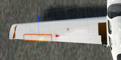
- Select the aileron object:
- Attach
Airfoilcomponent and tickIs Control Surfacein theAirfoilinspector.Airfoilgizmo will turn red.
- Adjust the
Airfoilif required.
- Attach one of the control surface components to the aileron, in this case
AileronControlSurface, and adjust its settings if needed.
- Select the wing
Airfoiland at the bottom of its inspector add theAileronControlSurfacefrom the previous step. This will tell the wing that the aileron belongs to it.
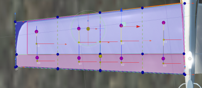
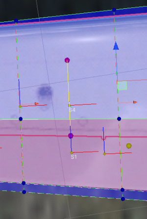
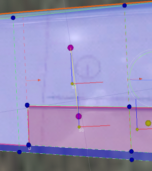
- Slicing of the control surfaces is controlled by the airfoil the control surface is attached to. In this case, that means that when the wing is sliced the airfoil will be sliced along the same lines too. This is required as the wing and the airfoil slices should roughly match up and these slices will get paired automatically. Paired slices between the airfoil and control surface are marked with a yellow line gizmo. This is required for a more realistic control surface simulation:
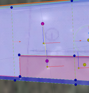
- Adjust the slicing points on the wing (red arrow handle) to match the edges of the control surface, an example:
- Assuming that the
AircraftControlleris set up pressing play will now result in a working aileron.
Note that control surface Airfoilss that are not attached to a fixed Airfoil need to have isControlSurface unticked as they act as standalone airfoils that can simply be rotated, instead of being a part of a wing.
Propulsion
Propulsion in NWH Aerodynamics consists of two main groups of classes; engines and propulsors. The engines are power generators while propulsors are power consumers. Examples of engine to propulsor pairings are:
TurbineEngine⇒JetPropulsorTurbineEngine⇒PropellerPropulsorPistonEngine⇒PropellerPropulsor- …
All engines can theoretically be paired to all propulsors.
Engines
Engines can be attached to any child object of an AircraftController but it is usually a good idea to create a dedicated empty GameObject for it. All classes inheriting from AircraftEngineBase have some common fields:
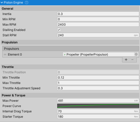
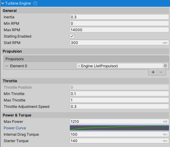
General
Inertia- determines how fast the engine will spin up/down. A larger value will take longer.Min RPM- minimum engine RPM. Different fromStall RPMas this is the minimum RPM the engine can turn at.Max RPM- maximum RPM the engine can achieve.Stalling Enabled- is it possible to stall the engine by running it at lower RPM thanStall RPM.Stall RPM- RPM under which the engine does not generate enough power to overcome internal friction causing it to stall. When starting the starter needs to be kept active until the RPM value goes overStall RPMor the engine will die.
Propulsion
Propulsors- list of objects inheriting fromPropulsorBasethat will get powered by this engine. This will be a single propulsor in most cases, such asPropellerPropulsororJetPropulsor. If multiple propulsors are attached, the power will be split between them.
Throttle
Min Throttle- minimum (idle) throttle. If the value is too low the engine might stall instead of idling.Max Throttle- maximum engine throttle. In most cases 1. Some aircraft can however go over 100% throttle for short periods of time, such as takeoff.Throttle Adjustment Speed- the speed at which the throttle is adjusted while increase/decrease throttle buttons are held.
Power & Torque
Max Power- maximum power the engine can generate.Power Curve- normalized power/RPM curve. Y axis represents power [0,1] and X axis represents RPM [0,1].Internal Drag Torque- torque as a result of engine losses. Larger value will result in engine that spins down faster but might not idle if the drag torque is larger from the generated idle torque.Starter Torque- torque generated by the starter motor. Larger value will spin up the engine faster. Start Time will also depend onInternalDragTorqueandInertia.
Piston Engine
Turbine Engine
Propulsors
Propulsors in NWH Aerodynamics take power from the engines and converts it into thrust.
All Propulsors have some common fields:
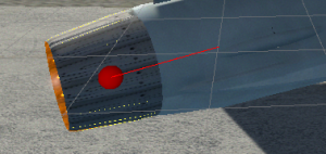
Thrust Point- a position at which the thrust will be applied. Marked with a red sphere.Thrust Direction- a direction in which the thrust will be applied. Marked with a red line (pointing towards the direction of force).Inertia- the inertia of the propulsor. A higher value will result in an engine/propulsor that is slower to spin up/down.Gear Ratio- some couplings between the engine and propulsor have a gearing ratio. A value of 2 means that for each turn of the engine the propulsor will do two turns.Rotation Direction- direction of rotation of the propeller.Reverse Thrust Coefficient- if the propulsor is spinning in reverse to the intended direction or the reverses have been applied the thrust will be multiplied by this value as the reverse thrust is normally lower than the forward thrust.
Propeller Propulsor
Jet Propulsor
Landing Gear
Basic Setup
- Set up
WheelColliders for each landing gear wheel as per Unity's guide. - Assign the created
WheelColliderto theWheelColliderfield. Assign the wheel transform (model representing the wheel) to theWheelfield. - Select the
Positionof the wheel (front, left, right, etc.) - Set the
Steer Angleif the wheel is steerable. Leave at 0 if not.
Rigging
For rigging to work properly a specific setup model setup is required with the following hierarchy:
- SuspensionArmUpper
- SuspensionArmLower
- WheelCollider
- WheelModel
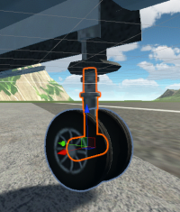
Assign the upper and lower suspension arm to the Uper Suspension Arm and Lower Suspension Arm fields.
The SuspensionArmLower should have rotation such that it's local Z axis points towards the pivot point of the SuspensionArmUpper:
Objects that move and steer with the wheel such as fairing can be added to the Static Transform field.
Animation
Landing gear that can extend/retract can use animation to achieve this. I will not be going over the steps to set up the animation as this is a standard Unity process and is explained quite well in the official tutorial here.
The default state for animation is extended landing gear. The default animation (going forward) is extended ⇒ retracted. Extending the landing gear is simply the retracting animation played in reverse.
Setup
- Tick
Retractableto indicate that the landing gear of the aircraft can retract. - Tick
IsExtendedif the initial state is extended landing gear. - Create new
AnimationController. - Add
Animatorto the objectLandingGearis attached to and assign theAnimationControllerto theControllerfield. - Add
Directionparameter toAnimationControllerand set the value to 1. - Create
AnimationControllerwithRetractLandingGearstate:
- Set the
RetractLandingGearstate speed to 1 and add a parameterMultiplierDirectionthat was created previously. - Create new
Animationand animate the landing gear as wanted. Initial state should be extended, final state should be retracted. - Assign the new
Animationto the previously createdAnimationController. - Assign the
Animatorto theAnimatorfield.
Sound
Sound in NWH Aerodynamics is handled through individual AircraftSoundComponents attached to the aircraft.
The main component AircraftSoundManager manages these components and handles mixing.
Sound is optional and does not have to be present for the AircraftController to work.
Aircraft Sound Manager
Engine Running Aircraft Sound Component
Engine Starting Aircraft Sound Component
Wind Aircraft Sound Component
Crash Aircraft Sound Component
Effects
Lights
Aircraft Lights Manager
Main light controller for the aircraft. All the lights are controlled from here.
Supported light types are:
- Landing Lights - beam lights lighting up the runway on approach.
- Strobe Navigation Lights - strong beacons that flash periodically.
- Constant Navigation Lights - lights with constant output indicating aircraft position and travel direction, usually red and green.
Strobe and constant navigation lights are toggled using the same keyboard key since they are normally on at the same time.
Each group can have multiple lights and they can be any type of Light or a Mesh can be used with Emission turned on. More about this in the LightSource section.
Light Source
One vehicle light source. Can be a Light or emissive Mesh.
- If
Lightis selected asTypeany UnityLightcan be assigned. It will be turned on and off according to user input. - If
Meshis selected asTypeanyMeshwithStandardshader can be used. It'sEmissionfield will be toggled to imitate a working light. Since this does not emit enough light to be a headlight usually another light source is used in tandem, this one withSpotLightassigned.
For an emissive mesh light to work it needs to be a separate object. If the model does not come with lights and blinkers as separate objects these will need to be separated in 3D modelling software such as Blender (free, open source).
When using Mesh light source make sure to tick the Emission checkbox on the material. This lets Unity know that this variant of the material is in use and should be included in the build.
Exhaust Smoke
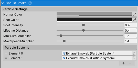
Particle effect that changes parameters based on the engine state. Requires an engine to be attached to the same object.
Interpolates between Normal Color and Soot Color based on engine state, while the Lifetime Distance determines the maximum distance a particle can travel from the starting position.
A ParticleSystem prefab called ExhaustSmoke is included with the asset under NWH ⇒ Aerodynamics ⇒ Effects ⇒ Particles ⇒ Prefabs ⇒ ExhaustSmoke.prefab and can be a good starting point to configuring the exhaust ParticleSystem.
Jet Propulsion Effects
This effect consists of two parts:
ParticleSystem- used to create an exhaust plume.Light- used to create exhaust glow that is normally caused by heat.
Requires JetPropulsor to work.
A ParticleSystem prefab called JetParticleSystem is included with the asset under NWH ⇒ Aerodynamics ⇒ Effects ⇒ Particles ⇒ Prefabs ⇒ JetParticleSystem.prefab and can be a good starting point to configuring the exhaust ParticleSystem.
Smoke System
The smoke trail left behind the aircraft, generally used for shows.
Trail Distance field determines how far in [m] behind the aircraft the particle trail will stretch while the Trail Max Lifetime and Trail Min Lifetime fields determine the minimum and the maximum particle lifetime. Particles will have the longest life when the aircraft is still or moving slowly and the shortest lifetime while the aircraft is moving fast because the Trail Distance will get met faster.
Instruments
Instruments can be used with a Canvas for UI or with 3D instruments for use in cockpits.
Check the Cirrus SR22 aircraft in the main demo scene for a configured cockpit instrument setup.
For the 3D indicators (non-canvas) to work properly they need to have the Z-axis set as the rotation axis in the 3D modelling software. If that is not an option it can also be done in Unity, guide here.
Airspeed
Setup
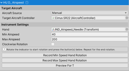
- Set the
Min AirspeedandMax Airspeed- these are min and max markings on the gauge. - Rotate the hand around Z-axis to the 0 position.
- Press Record Min Speed Hand Rotation to record the starting position.
- Rotate the hand around Z-axis to the max position.
- Press Record Max Speed Hand Rotation to record the final position.
- If needed tick
Clockwise Rotationto change the direction of the arrow travel.
Setup
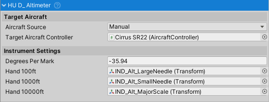
Altimeter
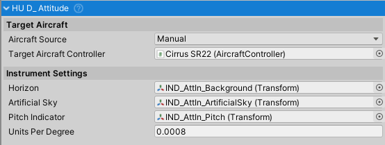
Attitude
Heading
Turn Indicator
Vertical Speed
Fuel
Setup
- Attach
VariableCenterOfMassto the aircraft if not already added.
- Attach
AircraftFuelManagerto the aircraft, preferably to the parent object (one containingAircraftController).
- Attach
AircraftFuelTankto an emptyGameObjectand position it to the rough location of where the fuel tank is on the given aircraft. Usually in the roots of the wings and in the fuselage. Position is important since it affects center of mass and inertia tensor.
- Attach
EngineAircraftFuelConsumerto any engines present on the aircraft.
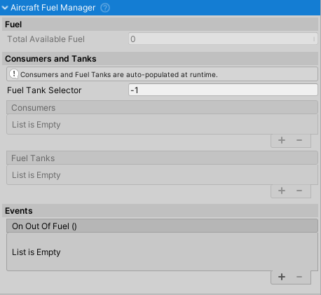
- Upon pressing play the
AircraftFuelManagershould show all the consumers and fuel tanks in their respective lists.
Aircraft Fuel Manager
Aircraft Fuel Tank
Implementation of IMassAffector that represents a fuel tank.
Used together with AircraftFuelManager to manage fuel levels on an aircraft.
