Airfoil
Airfoil class in NWH Aerodynamics is responsible for making the aircraft interact with air. It is sliced into smaller sections (AirfoilSection) which are then individually simulated using principles of 2D airfoil simulation.
If making an open-world game with a large-scale map (> ~4000 units), the shifting origin is required (not only for this asset, but in general with game engines that use floating point precision). Explanation.
Geometry
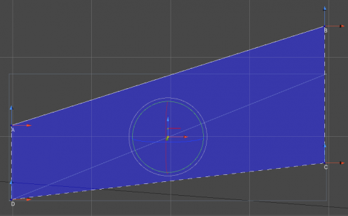
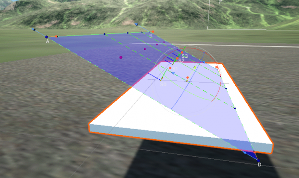
- Corners of this trapezoidal shape are marked A, B, C, and D - starting in the top left corner and going clockwise. Corners can be adjusted along the Y-plane of the
Airfoil, meaning only the 2D X-Z position can be adjusted along the 2D plane it is represented by. A blue-red movement handle is used for this. - To adjust the general position/rotation of the
Airfoiluse the position and rotation handles. - Each
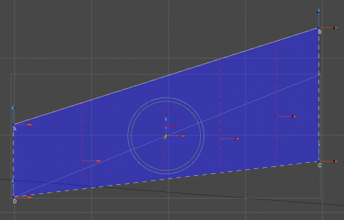
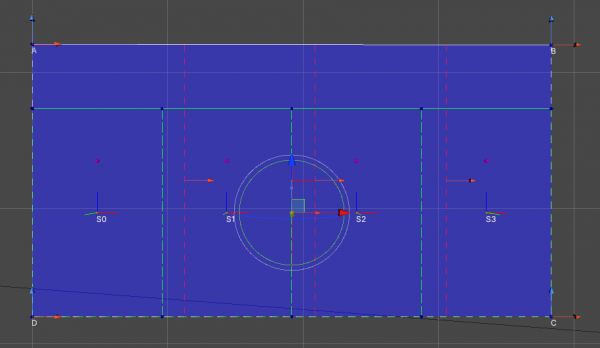
Airfoilis sliced along the slicing planes (dashed red lines in the image below) by pressing Slice button in the inspector intoAirfoilSections. Each section is then simulated separately during the play mode.
Shape
Airfoil uses its own geometry representation in a form of a 2D trapezoidal plane with relative position and rotation to the Transform it is attached to.
The shape of the Airfoil plane is adjusted using A, B, C, and D handle. AD and BC lines are always kept in parallel to each other.
If the shape of the airfoil can not be achieved using a single Airfoil multiple Airfoils can be attached to the object. This can be useful in cases such as a single-piece wing model. Still, the best practice would be to have one object and one Airfoil per single flight surface.
Slicing Planes
- Slicing planes are imaginary planes that slice the
Airfoilinto smaller sections. These are represented using dashed red line gizmos. - The position of each slice can be adjusted using the red position handle.
- Slicing planes are generated automatically but their number can be changed by adjusting the
Slice Countparameter and pressing Generate Slicing Planes afterward.
Sections
Once the slicing planes are set up pressing Slice button will generate AirfoilSections - sections of an Airfoil that each get simulated separately.
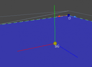
It is important that the orientation indicators of each AirfoilSection point in the correct direction. When flying level the blue indicator (forward) should point towards the incoming air, the red indicator (right) should be flush with the Airfoil and point towards the B-C line and the green (up) indicator should point up from the airfoil plane. If the green indicator is pointing the wrong way press the Flip button.
Position and Rotation
To adjust the position and rotation of the Airfoil plane in the relation to the Transform it is attached to, position and rotation handles can be used. These are similar to the Transform handles but only affect the Airfoil position and rotation.
Gizmos and Handles
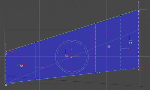
These are the gizmos used to represent an Airfoil inside the Unity Editor:
- A, B, C, D - corners of the
Airfoil.
- Green dashed lines -
AirfoilSections.
- S0, S1, S2, S3 -
AirfoilSectionnames (section 1, section 2, etc.).
- Blue, green, red lines -
AirfoilSectionorientation. Blue - forward, red - right, green - up. These correspond to the typical unity XYZ axis colors.
- Red dashed lines - slicing points / planes. Can be adjusted using the red arrow handle.
- Position and rotation handles - used to adjust position and rotation of the
Airfoilrelative to theTransformit is attached to.
- Yellow Sphere - positioned at the root of the position handle it represents the current
Airfoilposition.
- Purple Spheres - aerodynamic center of each
AirfoilSection.
Setup
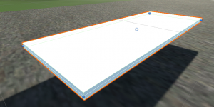
- As an example a primitive cube with a scale of [5, 0.1, 2] will be used to imitate a wing model:
- Add
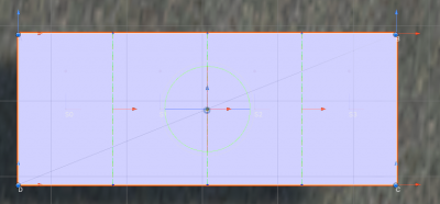
Airfoilcomponent to the wing.Airfoilwill try to automatically match the dimensions and orientation of the wing model:
- Airfoil automatically performs Orientate To Mesh, Fit To Mesh, Generate Slicing Planes and Slice steps when added. This process can be manually called by pressing the Auto button. In some cases a manual setup might be required (or wanted):
- Press Reset button to reset the
Airfoilto a 1×1 square shape (default). - Press Orientate To Mesh for the
Airfoilto match the mesh orientation. If the mesh does not resemble a wing this step will most likely fail. In that case, adjust the position and rotation of theAirfoilrelative to theTransformusing the position and rotation handles. - Press Fit To Mesh. This will position corners of the
Airfoilto match the shape of the mesh along theAirfoilplane. Adjust manually afterward if needed. - Press Generate Slicing Planes to (re)create slicing planes and adjust them if needed to match and control surfaces such as ailerons or flaps.
- Press Slice to slice the
Airfoilalong slicing planes intoAirfoilSections.
- If all went well pressing Play will result in a functional
Airfoil.
- If the
Airfoilis a part of an aircraft there is a large chance that a symmetricalAirfoilto this one exists on the other side of the aircraft. In that case, assign it (the other wing or the other horizontal stabilizer) to theMirroring Targetfield and pressMirror. This will create a mirrored copy of the current Airfoil on the otherGameObject.
Airfoil Profiles
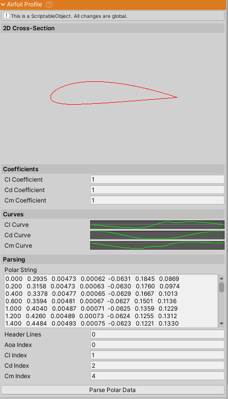
AirfoilProfile is a ScriptableObject that determines the behaviour of the Airfoil.
Fields
- 2D Cross-section - an icon of the 2D cross-section of the airfoil. Note that the Y dimension is exaggerated to better show the shape of the airfoil.
- Coefficients - Cl (coefficient of lift), Cd (coefficient of drag) and Cm (coefficient of moment) can be used to tune the base behavior of the
AirfoilProfile. These fields affect all theAirfoils using thisAirfoilProfile. For individual coefficient adjustment check theAirfoilinspector.
- Curves -
AnimationCurves representing the lift, drag and moment values along the Y axis against the angle of attack on the X axis. X axis should be in range of [-90, 90]. Usually parsed from thePolar Stringbut can also be set manually.
- Parsing - Converts polar data from 2D airfoil simulation software such as XFoil into curves.
Header Linesdetermines the number of initial lines to ignore (11 for XFoil) and the index values determine which column is what. By default the first column determines the angle of attack, next column is coefficient of lift, etc. If the curves are set manually this section can be ignored.
Included Airfoil Profiles
Over 1000 common airfoils are included.
After importing only NACA airfoils will be present in the NWH > Aerodynamics > Scripts > Airfoil > AirfoilProfiles directory but by double clicking on AirfoilProfiles.unitypackage in NWH > Aerodynamics > Scripts > Airfoil the rest of the AirfoilProfiles will get imported.
